
Difficulty: Advanced
Objective: When asked, what is the maximum angle I can print? The answer is - It depends.
From all my experience printing objects I have thought up what I call the wiggle theorem. It is an essential idea to know in 3D printing.

Here in Moscow, it is extremely common for women to wear high heels. And one of my pet peeves is when women wear high heels and can't walk normal. Here in Moscow, its likely can run on ice in heels, but in America i see women wobbling all over the place just by walking on a sidewalk and it drives me crazy.
When it comes to 3D printing you don't want your model to be wobble, you want them to be like a Russian in heels. Imagine trying to draw a picture in a rough car ride. Similarly a printer struggles to print on a moving, wobbly surface.

The typical answer to that question is 45 degrees. Others may say something like 60 degrees. But I have seen things print practically horizontally at like 90 degrees perfect. And I have seen things print at a small angle and fail. An that is why I came up with the wiggle theorem. It's not necessarily the angle but a mixture of things found in the wiggle theorem.
This becomes especially important in creating custom supports. A common mistake is to make a tall thin support so it breaks off easily. However even though it is printed vertically so and angle of 0, eventually the height will reach a point where it starts to wiggle and the printer misses the support.
The 3D Printing Ninja
3DNinjaneer@gmail.com
Objective: When asked, what is the maximum angle I can print? The answer is - It depends.
From all my experience printing objects I have thought up what I call the wiggle theorem. It is an essential idea to know in 3D printing.
Here in Moscow, it is extremely common for women to wear high heels. And one of my pet peeves is when women wear high heels and can't walk normal. Here in Moscow, its likely can run on ice in heels, but in America i see women wobbling all over the place just by walking on a sidewalk and it drives me crazy.
When it comes to 3D printing you don't want your model to be wobble, you want them to be like a Russian in heels. Imagine trying to draw a picture in a rough car ride. Similarly a printer struggles to print on a moving, wobbly surface.
How to make it not wobble?
Back to the example of the high heels, you have some factors that make up the heel.Diameter - if the heel is super skinny it will be harder to balance on.
Height - a small heel with a tiny diameter may be easier to balance that a really tall heel.
Angle- if your heel was angled its going to be harder.
The combination of these go into what I call the wiggle theorem. The reason it is important is because it answers questions like: What is the maximum angle before I need supports?The typical answer to that question is 45 degrees. Others may say something like 60 degrees. But I have seen things print practically horizontally at like 90 degrees perfect. And I have seen things print at a small angle and fail. An that is why I came up with the wiggle theorem. It's not necessarily the angle but a mixture of things found in the wiggle theorem.
This becomes especially important in creating custom supports. A common mistake is to make a tall thin support so it breaks off easily. However even though it is printed vertically so and angle of 0, eventually the height will reach a point where it starts to wiggle and the printer misses the support.
Experience is Key
Because every printer is different the results will greatly vary on what your printer is capable of and how much it will violate the wiggle theorem. A wise idea would be to test the limits of your printer. Many of these test can be found online such as:

In Conclusion
You want your model to remain stable and not wiggle at all while printing. Models fail when they become too thin, too tall, and have too much of an angle.Please leave your comments.
and as always thanks for visiting,The 3D Printing Ninja
3DNinjaneer@gmail.com
Difficulty: Intermediate
Objective: Learn about an excellent add-on to check your models in Blender for 3D printing. The most important check is to make sure your model does not have non-manifold geometry.


The 3D Printing Ninja
3DNinjaneer@gmail.com
Objective: Learn about an excellent add-on to check your models in Blender for 3D printing. The most important check is to make sure your model does not have non-manifold geometry.
3D Printing Toolbox
- Install the add-on in Blender called "Mesh: 3D Print Toolbox" by checking the box and then Save user settings.

- Be in edit mode of the object.
- On the left hand side window, [T], expand Print3D section.
- Input the settings of your printer's capabilities in the Checks section and then push check all.

For 3D Printing the most important checks are:
- Non-Manifold Edge (Holes)
- Intersecting Faces
- Thickness
These should all say 0 next to them. The other checks such as zero faces, zero edges, thin faces, sharp edges, etc. are not really that important.
Another Method of checking your model:
- Go in Edit Mode
- Open up your Properties Window [N]
- Check Mesh Analysis and choose the check
The faces that are colored are the faces that fail the check. The closer the color is to Red, the more of a problem it is. And the more the color is to blue, the less of a problem it is.
Once again the important checks for 3D printing are:
- Intersect(ing Faces)
- Thickness
Please leave your comments.
and as always thanks for visiting,The 3D Printing Ninja
3DNinjaneer@gmail.com
Difficulty: Noob
Objective: Learn various ways to fix non-manifolds.
To learn more about non-manifolds and the types see:Non-Manifolds: Your Worst 3D Printing Nightmare
To learn how to manually fix non-manifolds see: Non-Manifolds Manual Fixing Methods
The 3D Printing Ninja
3DNinjaneer@gmail.com
Objective: Learn various ways to fix non-manifolds.
To learn more about non-manifolds and the types see:Non-Manifolds: Your Worst 3D Printing Nightmare
To learn how to manually fix non-manifolds see: Non-Manifolds Manual Fixing Methods
Automatic ways of Fixing non-manifolds
Before you get your hopes up too high, realize that these are not perfect solutions and may not even fix the non-manifolds. I always recommend manually fixing your model, but if you do not have the skill or time there are plenty of justified reasons to do it automatically. That being said perhaps you may just get lucky with the following methods:
1.) Netfabb

This is a free (need a Microsoft account) online service where you can upload your model to be fixed and within a few seconds receive a fixed version. This is probably the easiest and best automatic method.2.) Meshmixer

This is a free program. What is nice about this program is that it lets you choose which non-manifolds it will fix individually. This can be done by going into "Analysis" --> "Inspector" , then this software will find non-manifolds:- The blue balloons are hole non-manifolds.
- The pink balloons are separate objects.
- The red balloons are all other types of non-manifolds.
You can click on the "Auto Repair All" to fix all the balloons at once. (Watch your model to make sure that the model does not change too drastically!)
You can also just fix individual non-manifolds by clicking on the balloons. If the balloon disappears then the problem is fixed. However if the balloon turns black, then the problem can not be fixed automatically. (Once again, watch your model to make sure that the model does not change too drastically!)
3.) Remesh / MeshLab
When there are lots of non-manifold errors, this is what I usually resort to. Your model will slightly loose the original shape, but usually it isn't too much.
1.) Netfabb
This is a free (need a Microsoft account) online service where you can upload your model to be fixed and within a few seconds receive a fixed version. This is probably the easiest and best automatic method.
2.) Meshmixer
This is a free program. What is nice about this program is that it lets you choose which non-manifolds it will fix individually. This can be done by going into "Analysis" --> "Inspector" , then this software will find non-manifolds:
- The blue balloons are hole non-manifolds.
- The pink balloons are separate objects.
- The red balloons are all other types of non-manifolds.
You can click on the "Auto Repair All" to fix all the balloons at once. (Watch your model to make sure that the model does not change too drastically!)
You can also just fix individual non-manifolds by clicking on the balloons. If the balloon disappears then the problem is fixed. However if the balloon turns black, then the problem can not be fixed automatically. (Once again, watch your model to make sure that the model does not change too drastically!)
3.) Remesh / MeshLab
When there are lots of non-manifold errors, this is what I usually resort to. Your model will slightly loose the original shape, but usually it isn't too much.
To learn how to remiss a model see this post: Remesh Tool: How to Convert a CAD File
Please leave your comments.
and as always thanks for visiting,The 3D Printing Ninja
3DNinjaneer@gmail.com
Difficulty: Intermediate
Objective: Learn various methods of how to fix non-manifolds. It is almost always better to fix non-manifolds manually because you do not lose the shape of your model. It is very difficult for a computer to automatically fix all types of non-manifolds at once because there are various types that require different treatments.
To learn about Non-manifolds and the types see: Non-Manifolds: Your Worst 3D Printing Nightmare
Automatic methods can be found here: Non-Manifolds Automatic Fixing Methods
Non-Manifold Video Tutorials
To learn about Non-manifolds and the types see: Non-Manifolds: Your Worst 3D Printing Nightmare
Automatic methods can be found here: Non-Manifolds Automatic Fixing Methods
Non-Manifold Video Tutorials
1.) Blender

- First you need to find the non-manifold: This can be done in Blender, in Edit Mode, by doing finger yoga pushing, [Ctrl]+[Shift]+[Alt]+[M] and the non-manifolds will become selected, highlighted. (You need to been in vertex selection for this to work, and wireframe view may help you spot the non-manifolds) Note: This will note find all the non-manifolds.
- (Better Option) Or you can install the Add-On, "3D Print Toolbox", Which I believe is essential for 3D Printing. This does an amazing job helping you avoid 3D Printing errors.
- Determine which type of non-manifold it is. This is done by wiggling the non manifold vertices until the problem can be seen. To see the types of non-manifolds see : Non-Manifolds: Your Worst Nightmare
- Fix the non-manifold using the following methods:
- Duplicate Vertices Non-Manifold:
Many problems occur because there are 2+ vertices on top of each other, when there should only be one. Text often has this problem. In the picture below, each of these highlighted vertices has an extra vertex in the same spot. By clicking remove doubles on the left hand side, it will fix this non-manifold. Note that only the selected vertices will be removed, hence you may want to select everything and then push "Remove Doubles". At the top center of Blender, you can find how many vertices were removed.
This can also be done a more custom manner by selecting 2+ vertices and then merging them together, by using the hot key [Alt]+[M], and choosing from that menu how to merge the vertices.

Essentially the "Remove Doubles" Tool mentioned previously is doing this just this. It finds vertices within a certain distance to each other and merges them together. To change the setting on how close vertices are to be affected by "Remove Doubles", you can adjust it after you push "Remove Doubles" and then change the merge distance as seen in the picture below. Note how the higher merge distance the more vertices will be merged together, and the more the object alters it's original shape. This can be seen in the image below as the circles went to triangles as the merge distance increased as opposed to the previous image.
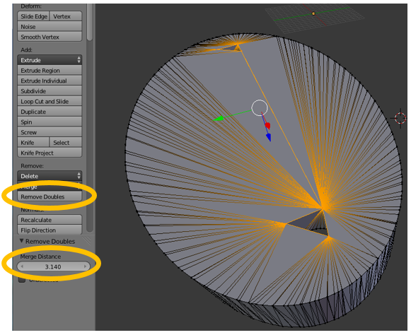 I will also mention that you can turn on a setting to automatically merge your vertices in Blender by going into Mesh-->AutoMerge Editing
- Hole Non-Manifolds:
These can be fixed by manually manipulating the geometry (deleting, filling, merging, etc).

Another more automatic way to fix holes is to go into Mesh --> Clean Up --> Fill Holes. Then depending on how big your hole is you may need to change the vertices count number in the bottom left as seen below. (For example if you hole has 8 vertices, then the number will need to be at least 8)

- Separate Part Non-manifold
These are fairly simple, you can just select the separate part and delete it (with [L]) . For more info see this post: How to Split & Separate a Model in Blender
- Intersecting Non-Manifold:
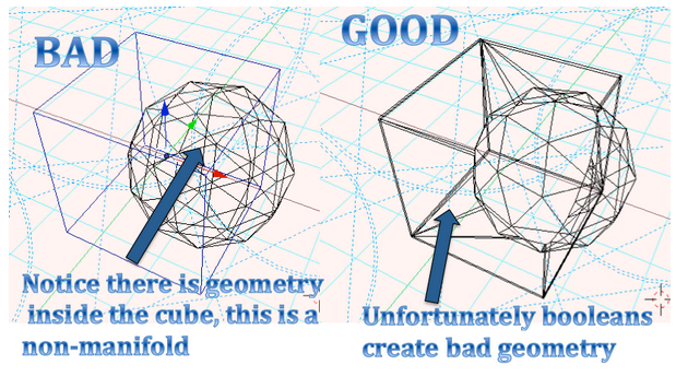
This is perhaps the most common, sneakiest non-manifolds of them all as it may not be detected as a non-manifold by the program. If you have multiple objects that intersect each other then you will need to fuse them together to create one part, not multiple parts intersecting one another. To learn how to fuse your separate objects together, see this post: http://3dprintingninja.blogspot.com/2014/11/boolean-trouble.html
Otherwise you will need to delete the faces and combine the two geometries into one, which is not an easy nor quick task.
- Infinitely Thin Non-Manifold:
Solidify Video Tutorial

This is technically a hole, but I choose this picture to show that an infinitely thin plane is any of the faces of this cube. To keep this shape (meaning keep 5 sides and not fill the hole) and fix this, you can use a "Solidify Modifier" in Blender that will thicken the faces of this cube, which will inadvertently fix the non-manifold. (You could also extrude all the faces as well...) This is shown in the image below.

- Inner Faces Non-Manifolds:
The best way is to just delete these faces manually. However there is a automatic way which may work by going into "Select" --> "Interior Faces"

- Sculpting to fix Non-Manifolds:
Sculpting can often fix-non-manifolds as it can also create them. However with the right touch it can be a great way to fix some non-manifolds. Review the tutorial on "Blender : Sculpt Mode" for more information found here: http://3dprintingninja.blogspot.com/2014/12/blender-curriculum-video-tutorials.html
Please leave your comments.
and as always thanks for visiting,The 3D Printing Ninja
3DNinjaneer@gmail.com
Difficulty: Intermediate
Objective: Learn what a boolean is and why to use it. Also learn how to fix boolean's that aren't working.


The 3D Printing Ninja
3DNinjaneer@gmail.com
Objective: Learn what a boolean is and why to use it. Also learn how to fix boolean's that aren't working.
What is a boolean?
A boolean is just a funny word that is a way to combine things. In blender the boolean modifier is used to combine 2 objects. When using the modifier the choices are: Union - combines the two objects into one, Difference - subtracts one item from the other, and intersect - only where both objects are. The pictures below illustrate:How to use a Boolean?
- Select the first object (Note that which object you choose first does make a difference)
- Add a Boolean Modifier
- Choose the second object (Note that which object you choose second does make a difference)
- Choose what type of Boolean Operation (If you don't suceed at first, try all of the operations, as sometimes the "wrong" one accomplishes what you want)
- Delete the old object, (If you do not, it will create a non-manifold that won't print)
Why is my boolean not working?
Non-manifold trouble
If either of your objects are non-manifolds, then the boolean will most likely not work. To learn more about non-manifolds see this post: http://3dprintingninja.blogspot.com/2014/07/non-manifolds-your-worst-nightmare.html
Many programs may create a new object when a boolean is created. Therefore make sure that there is only one object, and delete any items that should not be there. The first image below shows two objects before boolean. This would cause printing problems. The second is after a boolean modifier, this would print.
Normals
Using the properties window [N], you can visualize the normals, which basically means which way the face is facing. You will probably need to change the size of the normal in order to see them. Inspect the faces to make sure all normals are properly facing outwards.
Should a normal be the wrong direction you can flip the normal by selecting the face and then in the tool window, select Normal-->flip direction. If multiple normals are in the wrong direction you can select the whole shape and choose Normal-->Recalculate.
Non-mesh Object
Make sure that the objects that you are combining are meshes. Things such as curves and text are not mesh until they are converted. Convert the text [Alt]+[C] and then use a boolean modifier.
Improper Positioning
This is a silly problem, but emphasizes the importance of changing views as you model. A boolean modifier will not work if the objects are not touching. See the image below as it may appear touching on the left, but changing views we can see the two are not touching.Please leave your comments.
and as always thanks for visiting,The 3D Printing Ninja
3DNinjaneer@gmail.com
Difficulty: Noob


Objective: Understand what a raft is and when to properly use it.
What is a raft?
Rafts are similar to supports in the sense that they break off after printing. However supports are necessary, where as rafts simply enhance the quality of the print. A raft is extra material added to the print bed to print the object on.
Why should I use a raft?
1.) Reduce Warping
The most common reason for a raft is to absorb the warping so your object doesn't. Even though your object will still warp, it won't warp as bad. Seen below is the same object printed with and without a raft, except the job without a raft was canceled mid print. Notice the curl.

2.) Balance a Tall Object
This has to do with my Wiggle theorem, but suffice it to say it is bad if your object isn't stable. Therefore to stabilize your object you can add a raft to help it print better.
3.) Get an Object to Stick to the Bed Plate
Sometimes it can be difficult to get your print to actually start printing because it won't stick to the plate. There are solutions to this found in another post. However you can easily cheat the fix by simply adding a raft that the object will stick to.
When not to use a raft?
1.) Thin Objects
Rafts are easy to break off with a tall object, however when the object gets small you lose a lot of your leverage power, an it can be very difficult to break off the raft. In addition you may be just as likely to break your model as you are able to break the raft of.
2.) To Keep a Smooth Face
The best texture of your 3D printed object will usually always be the face of your object that lays flush with the print bed. By using a raft, that face will no longer lay on the bed, but flush with the raft.
Please leave a comment.
And as always thanks for visiting
3D Printing Ninja
3DNinjaneer@gmail.com
Difficulty: Advanced


Objective: Learn how to add supports and by which method.
What are Supports?
When I was in China I worked on site of constructing a manufacturing facility. In the picture above you can see the scaffling that we used to build it. (It was really scary as the thin bamboo would bend as you walked on it!) Scaffling is similar to supports, both are removed after the construction is complete, and necessary to construct it.
For those of you who do not have PVA filament capability on your printer, this is an essential blog for you. Supports are extra plastic that are printed for stabilizing and for areas where the printer would otherwise print on air. After printing the supports are broken off. This sounds easy enough but it is the hardest aspect of 3D printing. And unfortunately I have not yet come across a software that has a user interface that makes it easy to add supports and adds good supports.
How do I Add Supports?
(Methods of Adding Supports from best to worst)
1) Just don't. If you can design your model so that no supports are needed, then this is ideal. But this is often not possible. Therefore see if you can orient your object in a way that uses the least amount of supports.
2) Custom supports added as part of the model. Sounds easy, but requires the user to know where supports need to be added, how to add them, and how to make the supports. Overall it is an advanced method. But is the method I use and recommend.
3) Autodesk Meshmixer. Is for people who are willing to put the effort in one step ahead of using the printers settings for supports but not enough effort to make the supports themself. It is a way to add supports automatically much better than your printer will.
4) Default automatic supports on the printer's settings. Easiest method as you simply click yes to supports, but expect to spend the rest of your day trying to get those supports off. You'll break your model in half, slice your finger open trying to cut the support off. It aint fun.
There are usually advanced settings where you can adjust the settings of the automatic supports, but by this point you might as well use any of the methods above this.
Why are Supports So Difficult
1.) You have to know where to add supports and how dense to add them
2.) If you rescale your model size for printing it will also rescale the supports making them too small or large. Causing them to be too thin to print properly or too big to break off.
3.) When the model is sliced supports often confuse the slicer making strange codes for the printer.
4.) When breaking off supports you can easy break the part of the model off along with the support. Especially with small details.
5.) Since you are breaking off the support it will be noticeable. It will take after maching such as sanding to hide the rough spot where the support was broken.
6.) If you have a really complex model, the time need to add and take off supports can be a long time.
Feasible Designs of Supports
There are a few designs listed below that I have found useful. Lets say we want to print this cute little dragon:

The Beam
You can use a circle, square, triangle, I-beam, or whatever cross section. (I will mention that 3d printer that I use at work slightly struggles with circles so I like square cross sections).
The Thin Plane
Theses are easy and work well as long as they don't exceed a certain height. Once they become too tall they wobble too much and are not stable. However you can always taper the plane so that only the tip is thin.

The Ring
This is a mix of the beam and thin plane. This design is great because when you squeeze the cylinder it pops right off. I used it to print a goblet and it worked beautifully. The cylinders are not solid, they are thin as if you took the thin plan above and rolled the ends together.

The Tree
This is what Autodesk Meshmixer uses and is good because it doesn't waste as much material. Like the beam method except that it branches out both towards the object and the bed plate. This can be combined with any of the above, for example making a thin plane with holes in it, like a bridge truss. Perhaps this is the best method by optimization, but can be yer most time intensive.
When do you not need supports?
First of all anything that is horizontal will not need supports. I have seen printers bridge 6 inch gaps with just a little error. However to be on the safe side I would bridge no longer than an inch. Under such a bridge no supports would be needed. Please note that the bottom layer of the bridge must be horizontal and not slanted or arched.
Please leave a comment.
And as always, thanks for visiting.
3D Printing Ninja
3DNinjaneer@gmail.com
Difficulty: Intermediate
Objective: If you were so excited to see your finished print only to find that it didn,t print correctly, this blog should help. It covers very common problems and how to fix them.
Objective: If you were so excited to see your finished print only to find that it didn,t print correctly, this blog should help. It covers very common problems and how to fix them.
If the Prezi above isn't working properly, here is a link:
http://prezi.com/jpygdwnjd8vk/?utm_campaign=share&utm_medium=copy&rc=ex0share

Warping
You wanted a flat piece but it curls at the edges. Unfortunately there is not absolute solution to this, there are only ways to limit the warp. The easiest thing is to print an object again with a raft. The rest of solutions have to do with the printer itself.
Warping occurs due to the change in temperature from coming out of the extruder to room temperature. There fore you can try heating your bed plate or insulating your printer.
This is due to your printer moving too fast. Simply change the speed in the settings to be slower.
Bumps on smooth surfaces
Dis colored
This is due to the temperature being too hot and it begins to burn the material changing the color.
A blob of mess
The material most likely did not stick to the bed plate or the previously printed material. Therefore the printer continues extruding material but also moves the previous extruded material. So in the end it's just a mess and often the extruded is a mess as well.
Frozen and started melting the object
This is due to when programs crash. For example you may be on Excel and it crashes, then it may also crash the print job. Therefore if you are printing directly from your computer be careful not to do anything that will cause problems. Sometimes even opening a program like the task manager can crash the system.
Unfinished
The most likely problem is that the material ran out. Hence you should not start printing something unless you have enough material.
2.)The next most likely reason is that the material got jammed in the extruded. Unload the material and you will probably find rough markings and that the material is thicker in some regions than others.
The next most common reason is that the system was interrupted. The power went out, the computer was turned off, or the system just crashed.
Please leave a comment.
And as always, thanks for visiting
3D Printing Ninja
3DNinjaneer@gmail.com
Difficulty: Noob
Objective: The gcode is the easiest and most accurate way to predict how your part will print. Learn how to make gcodes, inspect them, and make them be one of your best 3D Printing Friends.

Just like google maps creates a path for a person to follow, a slicer software also creates a path to be printed upon. This is essentially what a gcode is. It tells the printer where to move, how fast to move, layer by by layer. The g-code is the most accurate prediction of what will be printed.


This happens most often at the first and last layers. In the picture shown below, you can see how the rough layer on the feet and between the legs of this cougar. It would look identical in the gcode 2D view.
Please leave a comment.
And as always, thanks for visiting,
3D Printing Ninja
3DNinjaneer@gmail.com
Just like google maps creates a path for a person to follow, a slicer software also creates a path to be printed upon. This is essentially what a gcode is. It tells the printer where to move, how fast to move, layer by by layer. The g-code is the most accurate prediction of what will be printed.
Creating a gcode
There are many options for a software to slice your model to be printed, such as Slic3r, Cura, or as I am using in the pictures, Makerware. These programs are free to download and take your model and convert it into a file that can be printed. To create the gcode of your file, import your model and export it as a gcode.
Inspecting the gcode
Next we take our gcode file that we just created and import it into a gcode viewer. There are multiple viewers, however I enjoy the free online viewer found at: gcode.ws
Drag and drop your newly created gcode file into the site. Loading bars should appear.
This is what it looks like:
3D Mode
Will display a 3D model constructed of the paths of each layer. It looks a little odd at first, but you'll get used to it soon. The most important thing is to rotate and zoom to get every angle so that you can spot the errors. Below are examples of what you are trying to spot.
Giant Holes / Missing Layers
This is the most common problem that you can see usually due to non-manifolds. Rotate your model until you see something as shown in the picture below. This means that nothing will be printing where the missing material is lacking. So don't print the file because it will look exactly like this.
Random Extra Material
This is rare and usually has little effect on the print and I have no idea what causes this. My best advice is to reorient the model and pick the least of the worst reoriented gcodes. Luckily most of the extra material is on the outside and can be broken off after printing.
Inner Material
Usually this is due to the software you used to make the gcode will want to add automatic supports inside the model.

Odd object
Some objects usually small or thin often have a hard time generating a good gcode. Here was a project that I was working on for a Math student. As seen below most there were obvious errors that were going to happen.
One way to fix this is to change the orientation of the model before you create the gcode. For example try rotating it 45 degrees about the x axis, try flipping it upside down, etc. Try a few orientations and then pick the best one.
2D Mode
This mode lets you look at each individual layer and the path the printer will take. You can also check the speeds of each layer, and if need be change the speed in advanced settings when you print it.
Also you may find it useful to look into the "2D Render Options" on the right hand side to make the view more clear.
Odd Layer
When a person mows a lawn they usually follow a pattern or some logic order. But imagine a person who decides to mow the lawn with a random pattern. This happens in 3D printing and to me it is hilarious and annoying. I just want to ask the software if they are drunk or on drugs because the path is so bad.

This happens most often at the first and last layers. In the picture shown below, you can see how the rough layer on the feet and between the legs of this cougar. It would look identical in the gcode 2D view.Gcodes do take a little more time, but in my opinion are worth it so that you do waste time and material printing something that you could have know would have not printed out well.
Please leave a comment.
And as always, thanks for visiting,
3D Printing Ninja
3DNinjaneer@gmail.com
